recalLED - PCB Simon Says Game
This is article was originally posted at the start of 2019. It was bit long so I decided to rewrite it. I hope you enjoy it.
Last year I used my new purchased 3D Printer to make custom lithophanes as Christmas gifts for my family which went very well. So this year I thought I would use my new found electronics knowledge to create something. That thing would be a PCB Simon Says game powered off a coin cell, this was inspired by a Reddit post about the same game. I decided to use the Attiny85 due to its low power, small pin count, Ardunio compatibility and to learn something.
The game consists of four different coloured LEDs with a button related to each one. The microcontroller will blink the LEDs in an order and then the user will have have repeat back that order using the buttons. The first level will have a combination of four, second level will have five etc until you get the combination wrong. Then it will start over again.
To make this happen I started with the hardware, which involved connecting the buttons and LEDs to the 8 (4/5 GPIO) pin microcontroller. I found a couple of methods to do this, one is using a resistor ladder and the built in ADC for the buttons along with multiplexing the LEDs. The second was to use one pin per LED/button while making use of tri-state of the pin to control them. This method lead to button presses also turning on the LED which is a positive for this project as this would have to be added in software anyway, so this method was chosen.
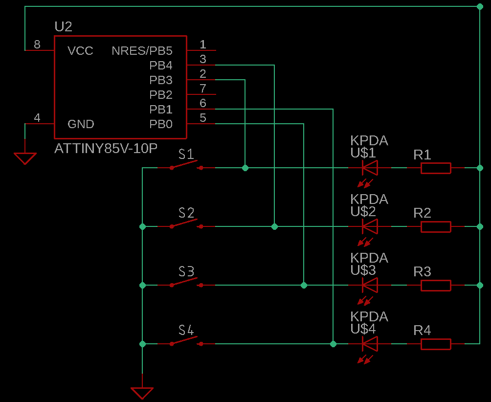
How it is as follows, the LEDs are controlled by using the microcontroller as a current sink. The positive side of the LED is connected to a current limiting resistor which is connected to the power supply. The negative side of the LED is connected to a pin of the microcontroller. To turn the LED on the microcontroller just has to pull that in low. This allows the microcontroller to sink current, completing the circuit and lighting up the LED. The buttons work by one side being connected to the negative side of the LED and the other to ground. To see if a button has been pressed the microcontroller sets the pin to an input making it high impedance input with an internal resistor and measures the voltage on that pin. When the button isn’t pressed the pin will be floating and when pressed it will be at ground, 0V.
The basic program was written for an Arduino Uno to test out the functionality while waiting for the Attinys to arrive. Once I got the Attiny85s, I burnt the bootloader and uploaded the program using my Arduino Uno as an ISP once the code had been adjusted for the Attiny.
Now the circuit is working on the breadboard with the Attiny, I turn the schematic into a PCB using Eagle (I have since moved KiCAD). Originally I used all surface mount with the plan on using a programming clamp to program the microcontrollers in circuit however I had little luck with that method and had to order new PCBs. These had through hole footprints for the Attiny which allows me to program them on the breadboard before soldering them in place. This also give me a chance fix other issues with the original PCB.
While waiting for the new PCBs to arrive, I continually improved the code by implementing a few extra features such as a persist high score that was saved to EEPROM. On boot the LEDs would flash your high score. I also replaced most of the Arduino functions with register manipulation, this change wasn’t necessary but was good to learn.
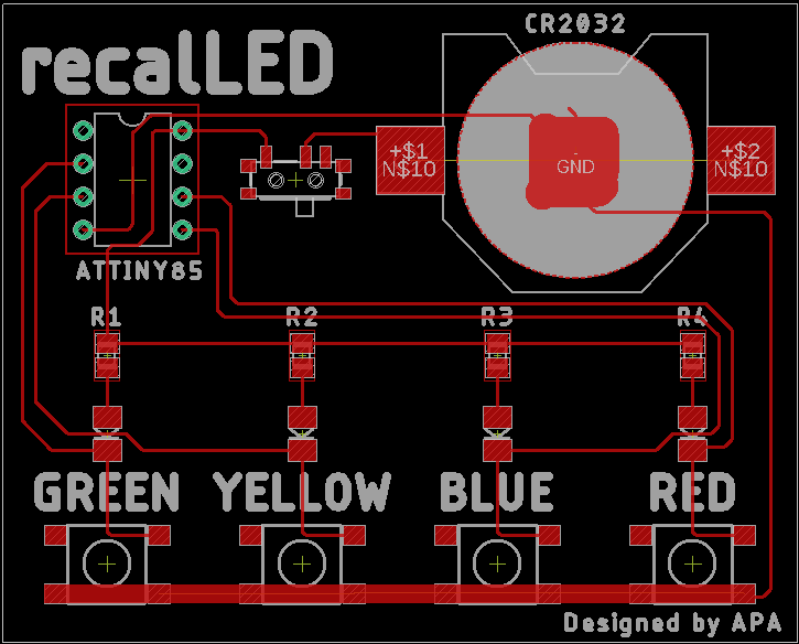
The PCBs arrived and worked perfectly, one down only seven more to go. Once the soldering was done and the all the PCBs where tested, I had sometime left. So I open up Soildworks and made a simple case with a friction fit lid and printed them in PLA on my 3D Printer. Each gift recipient got a custom case with their name debossed on the lid. Over the next few days my printer ran non-stop and finished just in time, the case was still warm as I put into my suitcase. The last thing to do was to print off little instruction booklet to stick in each box and then wrap them. Then I was done, just need to hand them out on Christmas. The final product
Giving them out over Christmas was a great. Seeing my Nan sitting their playing it for 10 mins or so was great, along with watching the rest of my slightly inebriated family try and get past the first few levels. I am very happy I took on this project and I learnt a lot from it. Always double check schematics before sending it off, programming surface mount chips at home is hard, game design isn’t as easy as it seems and many more. I am looking forward to next year Christmas project. I am thinking something more decorative next year. If you have any questions or suggestions, please comment below.